Understanding Control Components of the Masterpact Square D NW Breaker
The Masterpact Square D NW circuit breaker is a crucial electrical device used in various electrical applications. Understanding its control components is essential for safe and efficient operation.
To delve deeper into its functionality, we’ll explore the control circuit options and associated identification codes. In this article, we’ll break down these codes, share a fun fact about the breaker, and emphasize the importance of matching control components with the correct voltage for your system.
Cracking the Masterpact NW Breaker Code
To better understand the Masterpact NW breaker, let’s decipher the identification codes for its control components:
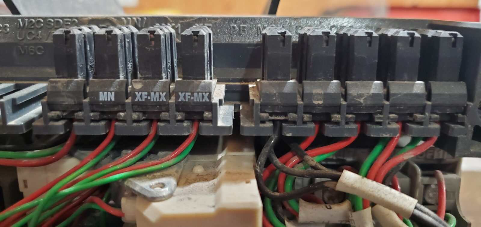
1. MX – Shunt Trip: The MX code represents the shunt trip function. This component plays a role in opening the breaker when needed, typically triggered by an overload, short circuit, or external control signal.
2. XF – Shunt Close: The XF code stands for shunt close. Unlike the shunt trip, this component helps close the circuit breaker. The shunt close provides the extra closing force needed to overcome friction in the breaker mechanism, which can increase over time due to wear and tear, and manage the initial surge in current, ensuring a secure and reliable closure.
3. MN – U.V. Under Voltage Coil: The MN code corresponds to the undervoltage coil, which monitors and responds to voltage changes. If the system voltage falls below a predetermined threshold, the undervoltage coil trips the breaker open, protecting equipment from damage caused by low voltage conditions.
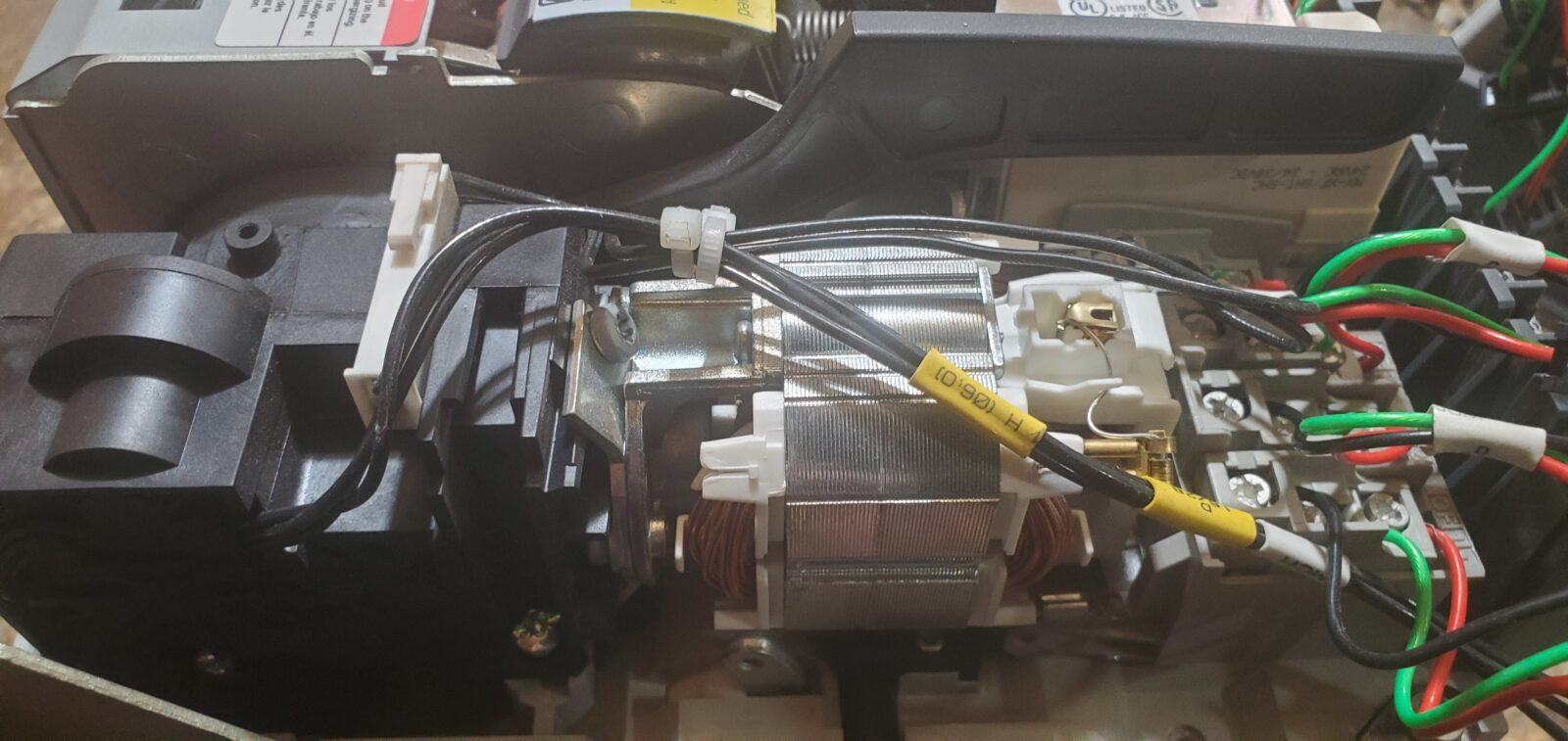
4. MCH – Charging Motor: MCH denotes the charging motor, an essential part of the breaker’s operation. It is responsible for compressing the spring within the closing mechanism. This stored energy is then released when the breaker needs to close.
A Fun Fact
Here’s a surprising fact about the Masterpact NW circuit breaker: the shunt trip (MX code) and shunt close (XF code) coils, although seemingly opposite in function, share a surprising secret – they’re actually interchangeable parts! This might seem counterintuitive, but the key lies in their placement within the breaker mechanism.
Think of these coils like tiny electromagnets. When energized, they create a magnetic field that interacts with the circuit breaker’s internal mechanics. However, the location where you install the coil determines its specific role.
- Shunt Trip (MX): Mounted in a specific location, the MX coil engages a mechanism designed to trip (open) the breaker contacts. When energized, the magnetic field from the coil pulls on a designated latch, releasing the spring-loaded closing mechanism and forcing the breaker contacts apart.
- Shunt Close (XF): By flipping the script and installing the same coil (MX) in a different location within the breaker, it engages a separate mechanism designed for closing. In this scenario, the magnetic field from the energized coil interacts with a different latch, releasing the stored energy from the charged spring mechanism. This surge of energy drives the breaker contacts together, effectively closing the circuit.
It’s like having a single key that can unlock two different doors depending on where you insert it. In the NW breaker, the interchangeable coil acts as the “key,” while its placement determines whether it unlocks the “trip” or “close” function. This clever design offers some flexibility during maintenance or troubleshooting. A qualified electrician can swap the coil’s location to convert it from a trip to a close function (or vice versa) if necessary.
Breaker Cradle Position Indicators (CD, CE, CT)
MasterPact NW drawout breakers can report their physical position in the cradle using auxiliary cell switches:
- CD – Breaker is Disengaged (withdrawn)
- CE – Breaker is in Test position (connected electrically but not to the load)
- CT – Breaker is Connected (to both control and load circuits)
These switches help automate status feedback in remote monitoring systems.
Coil Specifications – Quick Reference
| Coil | Function | Voltage Range | Duty Cycle | Notes |
| MX1/MX2 | Shunt Trip | 24–480 Vac, 12–250 Vdc | Momentary (≤ 0.5s) | Avoid >10 ft runs |
| XF | Shunt Close | Same as MX | Momentary | Use with PF contact |
| MN | Undervoltage | 0.35–0.7 Un trip | Maintained | Reset at >0.85 Un |
| MCH | Spring Charging | N/A | Auto | Manual option with handle |
Wiring Tips & Terminal Layout
Proper wiring is key to getting the most out of your MasterPact NW’s secondary controls. Here are some field-tested tips that help maintain reliability and protect components:
- Use terminals C2/A2 for connecting shunt trip (MX1), shunt close (XF), and undervoltage (MN) coils.
- Keep wiring runs under 10 feet (3 meters) to reduce the risk of control failure due to induced voltage.
- For runs longer than 10 feet, use an interposing relay to maintain signal integrity.
- Energize control coils (MX, XF) for no more than 0.5 seconds to prevent coil damage.
View Official Wiring Diagram
For detailed visuals of the terminal layout and coil wiring, refer to the Schneider Electric catalog:
View Wiring Diagrams from Schneider Electric
Wire Length by Coil Voltage
To ensure proper coil function and avoid signal degradation, follow these maximum wire lengths:
| Coil Type | Voltage | Max Wire Length | Recommended Wire Gauge |
|---|---|---|---|
| MX1 / XF | 24 Vdc | 16 ft (5 m) | 14 AWG |
| MX1 / XF | 48 Vdc | 26 ft (8 m) | 14 AWG |
| MX1 / XF | 110–125 Vdc | 66 ft (20 m) | 16 AWG |
| MN | 24 Vdc | 33 ft (10 m) | 16 AWG |
For longer runs, install an interposing relay near the coil to ensure proper energizing.
MN Delay Module
The undervoltage release (MN) coil can be fitted with a time-delay module (adjustable from 0.5 to 3 seconds). This prevents nuisance tripping during short voltage drops.
Commonly used in facilities with known power fluctuations or during load transfers.
Remote Operation Options
There are two ways to control the MasterPact NW breaker remotely:
1. Direct Coil Control (C2/A2 Terminals)
Use pushbuttons or PLC relays to energize coils (MX1, XF) directly via C2/A2. Ensure momentary contact only.
2. Communication Control (C3/A3 Terminals)
In communication-enabled breakers, coils connect via C3/A3 terminals. All open/close commands are managed by the communication module.
Tip: Coils on C3/A3 are only energized after the breaker logic confirms safe operation conditions.
Understanding Auxiliary Contacts (OF, EF, PF)
Auxiliary contacts in the MasterPact NW breaker help indicate its status and ensure safe operation. Here’s a breakdown of the key types:
- OF (Open/Closed Contact):
This contact shows whether the breaker is open or closed. It’s commonly used in control panels to send status signals to a PLC or remote monitoring system. - EF (Closed Contact):
EF confirms that the breaker is both closed and connected. This is important for ensuring full engagement before allowing power flow or further commands. - PF (Ready-to-Close Contact):
PF indicates the breaker is ready to accept a closing command. It ensures that the spring is fully charged and no trip conditions exist. It’s often wired in series with the XF (close) coil to prevent the breaker from closing under unsafe conditions.
Why This Matters:
Using these auxiliary contacts correctly helps:
- Prevent unsafe operation
- Enable remote monitoring
- Ensure safe sequencing in control logic
Installation Tips That Help You Work Smarter
When it comes to wiring and configuring secondary controls on the MasterPact NW breaker, a few simple steps can make a big difference in performance and safety. Here’s what we recommend based on experience and manufacturer best practices:
- Match the voltage: Always confirm the coil’s rated voltage matches your system before applying power. It sounds simple—but it’s often overlooked and can cause major issues.
- Keep wiring short and efficient: For shunt trip (MX), shunt close (XF), and undervoltage (MN) coils, keep wiring runs under 10 feet. Longer runs? Use an interposing relay to avoid induced voltage problems.
- Use the PF contact with the XF coil: This prevents pump-closing—a condition where the breaker tries to close repeatedly due to a misfired control signal. It’s a small wiring decision that adds major protection.
- Allow time for the spring-charging motor: After a closing operation, the MCH motor takes about 4 seconds to recharge the spring. That’s normal—just make sure your logic or operator timing accounts for it.
- Plan for transient protection: If you’re using the undervoltage release (MN), consider adding a delay unit to prevent nuisance trips from momentary voltage dips.
MCH – Spring-Charging Motor Specs
| Feature | Value |
|---|---|
| Voltage Range | 24–480 Vac / 24–250 Vdc |
| Power Consumption | 180 VA |
| Charging Time | ~4 seconds |
| Operating Rate | 3 cycles per minute (max) |
| Mechanical Life | 10,000 operations |
This motor automatically charges the closing spring after each operation. Manual charging is also available with a handle.
Why It Matters:
These aren’t just suggestions—they’re proven steps that help you get the most out of your MasterPact NW while keeping your control system safe, efficient, and built to last.
A Word of Caution
The world of electrical components may seem complex, but a single misstep can have serious consequences. When dealing with control components for the Masterpact NW breaker, voltage matching is paramount. Here’s why:
- Safety First: Control components are designed for specific voltage ratings. Using a mismatched voltage coil can lead to malfunctions that compromise safety. For example, a low-voltage coil designed for a 208V system wouldn’t generate enough magnetic force in a 480V system.
- Ensuring Reliable Operation: Each voltage rating corresponds to specific operational characteristics. A mismatched coil wouldn’t function as intended, potentially causing the circuit breaker to trip or fail to close at the correct time. This could disrupt critical processes or even damage connected equipment.
- Identifying Voltage Requirements: Fortunately, determining the correct voltage is straightforward. The voltage rating is typically printed directly on the plastic label of the control component you’re replacing. Additionally, the NW circuit breaker’s technical specifications or user manual will also list compatible voltage ratings for its control components.
Understanding the control components and identification codes of the Masterpact Square D NW breaker is vital for its proper operation.
By learning about these control components their interchangeability, and adhering to voltage requirements, you can ensure this essential electrical device’s efficient and safe functioning. Whether you’re a seasoned professional or just starting in the field, this knowledge will help you harness the full potential of the NW circuit breaker in your applications.
Final Thoughts
Understanding the control components of your Masterpact NW circuit breaker is a valuable first step… But if you’re looking to get hands-on and replace a worn-out MCH (charging motor), we’ve got you covered!
Our video takes you through the process step-by-step, showing you how to remove casings and detach the old motor, as well as how to put the new one in correctly and test that it’s working properly. See you there!
Need guidance on your setup?
We’ve supported professionals like you for over 25 years with dependable answers and practical solutions.
Whether you’re troubleshooting an existing panel or planning a new install, we’re just a message away.
👉 Contact our team for tailored support or explore more helpful insights in our breaker control library.
Let’s keep your operations running smoothly—with solutions you can count on.